
Hazards Associated with Overshots
By Colin Rice · Colin Rice Exploration Drilling Advisory · www.colinrice.co.za
This article examines some of the most significant hazards associated with overshots.
This is the fourth article in our Technical Series on Wireline Retrieval Operations. Click here for an outline of the entire Technical Series on Wireline Retrieval Operations.
This article continues from the previous one which detailed the hazards relating to inner-tube head assemblies.
A variety of things can go wrong in the process of retrieving and deploying a wireline inner-tube assembly. This article examines some of the most significant hazards associated with overshots.

Illustration to show the lock nut fitted to the top of the jar staff.
The jar staff and jar tube may separate
The previous article explained that the jar staff and jar tube allow the driller to deliver an impulse to the spearhead to try to release the latches of a stuck inner-tube head assembly.
The top of the jar staff and the bottom of the jar tube are therefore subjected to relatively large impact forces and these components must be able to absorb these impact loads.
If either the top of the jar staff or the bottom of the jar tube were to fail, then the overshot could separate and fall in an uncontrolled way.
In most standard overshot assemblies, the top of the jar staff is threaded and a lock nut is used as the point of impact for the jar tube. If the lock nut becomes loose, the jar staff will slide out of the jar tube.
In other designs the jar tube is fabricated so that the oversized top of the jar staff and the jar staff itself are one solid steel component. This construction is substantially stronger than the threaded bar and lock nut arrangement and so it is recommended that overshots with this type of construction only are used.
The bottom of the jar tube has to be reduced in diameter to allow the jar tube to slide inside of it. In most overshots this reduction in diameter is achieved by welding a thick steel “washer” to the base of the jar tube. If the base of the jar tube were to break, the jar staff could slide out of the jar tube.
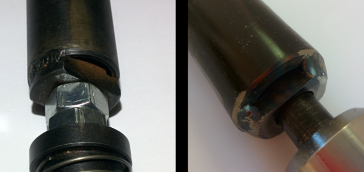
The base of the jar tube has a welded washer that retains the jar staff in position. The base can be subjected to severe impact loads when the overshot is jarred and so secure welding is necessary to ensure that the base does not break off the jar tube.
The quality of welding varies from manufacturer to manufacturer and also with the grades of steel used in the construction of the jar tube. It is recommended that close inspection of the jar staff head and the jar tube base becomes a part of the daily inspection process.
The jar staff attachment and overshot head may separate
The jar staff attaches to the overshot head in two possible ways and both methods of attachment have associated risks:
The end of the jar staff is held in the overshot head using two spring pins or,
The jar staff screws into the overshot head and is locked in position using a lock nut.
Manufacturers used to use two spring pins to secure the jar staff and overshot head, but newer overshot designs require that the jar staff is screwed into the overshot head and is held in place with a lock nut. The problem is that if the lock nut loosens it is possible that the jar staff will completely screw out of the overshot head.
Manufacturers have introduced different methods of locking the jar staff but none are completely fool-proof. Daily inspection of this critical attachment is therefore essential.

The jar staff is retained in the overshot body in two ways; it may be screwed in and retained with a lock nut or it may be retained using two spring pins.
The cable swivel assembly may fail
The cable swivel assembly is the top-most part of the overshot and is the point of attachment of the overshot to the wireline rope.
The cable swivel assembly screws into the top of the sinker bar and incorporates a bearing which allows the assembly to rotate and so release any spin that may build up in the wire rope. Because there is a bearing in the assembly, there is a grease nipple that allows the cable swivel assembly to be properly lubricated. Frequently however, the bearings are not greased and this results in significant wear in the swivel assembly. If the wear is so great that the assembly breaks then the inner-tube and overshot can fall in an uncontrolled fashion.
The attachment at the cable swivel assembly is also made-up to create a weak point in the wire rope. This is so that in the event that the inner-tube assembly becomes stuck in the drillstring and the driller increases the pull on the rope, then the rope will snap at the cable swivel assembly. This will allow all of the wire rope to be removed from the drillstring before it is tripped.
Grease nipple to ensure adequate lubrication of the bearing inside the cable swivel assembly. Note that the grease nipple is broken and has clearly not been lubricated for a very long time
The wireline cable may break
Various sizes and constructions of wire rope are used in diamond drilling operations but all wireline rope suffers accelerated abrasive wear due to poor spooling onto the winch drum. Abrasive wear coupled with shock loading can cause the wire rope to fail and, depending upon where the failure takes place, it may be necessary to thread the rope through the sheave before it is reattached to the other end of the rope.
This may mean that a member of the drill crew has to ascend the mast or it will entail lowering the mast into a horizontal position. Both of these operations introduce their own set of associated hazards and risks. Breakage of wireline rope during normal retrieval operations must therefore be avoided - regularly inspection and removal of defective sections is therefore a critical part of the wire rope maintenance procedure.
When defects are detected in a wireline rope it is common practice to cut out the defect and then re-join the rope. This practice could not be tolerated in a hoist rope but, because of the cost implications and the risk attached to the practice, it is acceptable for wireline ropes. It is essential however that the mechanism to re-join or splice the wire rope is correctly engineered and that it returns the connection or splice to the same strength as the rope itself.
Again, different drillers have different methods of re-joining rope and it is essential that the contractor decide on one particular method and that he consistently applies that method across all drill rigs. As was the case with the rope termination at the cable swivel assembly, this procedure must be documented in a standard operating procedure and all required personnel must be trained in the procedure.
Breakage of wireline rope during normal retrieval operations cannot be accepted and so any breakage of a wireline rope (other than deliberately breaking the rope at the weak point at the cable swivel assembly) must trigger a thorough inspection of the entire spool of rope and if defects are identified, these must be repaired using the rope re-joining procedure.
The inner-tube assembly may be pulled into sheave wheel
This is probably the most significant hazard associated with wireline retrieval – an inner-tube assembly pulled into the sheave wheel will result in the wireline rope stripping out of the cable swivel assembly and so the inner-tube and overshot will fall in an uncontrolled manner.
Drillers secure a piece of flagging tape 30 or so meters above the overshot to act as an indicator that the pvershot assembly is about to reach surface. The driller will then slow down the winch to prevent the assembly being pulled into the sheave.
While this method has been used for many years, we have to implement a more reliable method of ensuring that the inner-tube assembly is not puked into he sheave. The most elegant way of doing this is to fit a trip switch system - this switch is mounted on the mast and suspends the pulling effect of the winch once the overshot hits the switch. Effectively, the switch acts as an automatically activated emergency stop switch.