
Wireline Retrieval Operations
By Colin Rice · Colin Rice Exploration Drilling Advisory · www.colinrice.co.za
In order to fully appreciate the hazards associated with wireline retrieval, a thorough understanding of the process is required. This article explains the processes involved as a starting point for a better understanding of the associated hazards.
This is the second article in our Technical Series on Wireline Retrieval Operations. Click here for an outline of the entire Technical Series on Wireline Retrieval Operations.

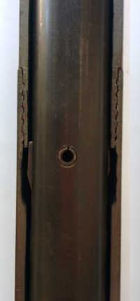
The wireline retrieval system consists of a number of essential components all of which have to be carefully designed, operated and maintained to ensure safe and efficient inner-tube retrieval.
Unfortunately, none of the wireline retrieval equipment currently available is standardised and so variations in design, component dimensions and quality of manufacture exist. Components from different manufacturers are not interchangeable and mixing critical components will introduce significant risk to the operation.
The most important components in a wireline retrieval operation are the:
wireline winch
wireline rope
wireline rope spooling system
method of connecting the wireline cable to the overshot
overshot and,
inner-tube head assembly
The inner-tube head assembly performs two main functions in the drilling cycle:
it provides a means of locking the inner-tube into the corebarrel while the drill string advances.
it provides a means to enable the inner-tube to be retrieved at the end of the drilling cycle.
The inner-tube head assembly is screwed directly to the inner-tube and this entire assembly is deployed downhole through the open drillstring. The inner-tube assembly descends through the drillstring until the upset on the latch body seats in the landing ring. The landing ring limits the downward movement of the inner-tube assembly and with the upset on the latch body it provides a water seal that prevents water by-passing the inner-tube assembly.
When in the landed position a pair of spring-loaded latches open and lock the inner-tube assembly in the corebarrel.
When the inner-tube assembly is descending through the wireline drill rods the latches are forced into a closed position by the drill rod but when the assembly reaches the corebarrel and seats in position the latches are allowed to open into a machined recess in the top of the adaptor coupling. When open, the latches butt against the bottom of the locking coupling and this prevents the assembly being pushed back up inside the drill rods as the drillstring advances.
Wireline inner-tube latching mechanism

The latches are held inside of the drillstring.
The inner-tube has descended further and is about to land in the landing ring.

The inner-tube has landed and is seated in the landing ring – in this position, the latches open outwards into the recess milled into the top of the adaptor coupling. Note how the top of the latches are stopped from moving upwards by the shoulder on the base of the locking coupling.
A series of bearings allow the upper portion of the inner-tube head assembly to rotate relative to the lower section and so, as the drillstring rotates, the top portion rotates while the lower section or inner-tube remains stationary.
When the inner-tube is full, drilling is stopped, the quill rod is backed off and moved away to allow access to the open drillstring. The overshot is then lowered on the wireline cable through the open drillstring.
The overshot has a pair of lifting dogs that engage the base of the spearhead point and provide a shoulder to allow the inner-tube assembly to be hoisted to surface. When an upward pull is exerted on the overshot by the wireline rope, the latch retracting case moves upwards and in so doing retracts the latches which then frees the inner-tube assembly. The entire assembly is then pulled to surface through the open drill rods.
Once the inner-tube and overshot assembly have been retrieved to surface they are pulled clear of the open drill rods and then outwards away from the drill rig so that the assembly can be laid down in a horizontal position to facilitate easier inner-tube disassembly and core removal.
Once laid in a horizontal position, the inner-tube is disassembled and the core is removed from the inner-tube. The inner-tube is then reassembled, hoisted back into a vertical position and dropped through the open drillstring, it floats down through the drilling fluid inside the drillstring and eventually again latches in the corebarrel. The next core run can then commence.
All of these processes expose operational staff to risk – The following article examines some of these risks.